Powering a MicroRider Instrument: Startup and Shutdown Sequence
The MicroRider is a small instrument package for turbulence microstructure measurements, designed to integrate with a variety of marine instrument carriers, such as Gliders, AUVs, moorings, CTD rosettes, profiling floats and the WireWalker.
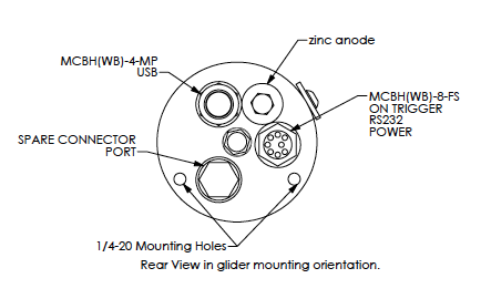
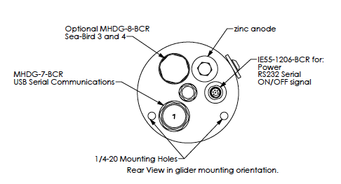
Depending on the age if your MicroRider instrument, it will either have an IE55-1206-BCR or a MCBH(WB)-8-FS connect on the rear end-cap. This connector serves as the power supply, RS232 serial output and ON/OFF signal for the MicroRider. 

To power on your MicroRider, here is the startup sequence:
Using the connection to the IE55-1206-BCR or MCBH-8-MP connector, where:
Pin 1: +12VDC Power
Pin 2: Power Ground
Pin 3: Not Connected
Pin 4: Not Connected
Pin 5: RS232 TX
Pin 6: RS232 RX
Pin 7: ON Signal
Pin 8: ON Signal Return
- Connect the Power to Pin 1 and Pin 2. This power must always be available (on and live) to the MicroRider. The power supply board has a low power watchdog circuit that checks the power.
- If the power voltage is OK (within limits) than the power supply board waits for the ON signal to be activated.
- The ON signal is connected to Pin 7 and Pin 8. It is either done by shorting across Pin7 and Pin8, or by sending a small current (1mA – 2mA) into Pin 7 and return on Pin 8.
- When the ON signal is detected by the power supply board it energizes the MicroRider.
- The internal computer boots up.
- At this time the customer RS232 connection on Pins 5/6 through a terminal program (Motocross) can be made so the customer has manual control of datalogging. Or, the computer can be set up so it automatically starts datalogging.
- To safely shut off the MicroRider the customer must stop datalogging.
- Then remove the ON signal which tells the power supply board to shutdown.
- The MicroRider goes back to the very low power watchdog state waiting for the next ON signal.
Basically:
- Power must always be available
- ON/OFF is controlled by the user through a shorting switch or using a small current driver
- Datalogging is either started automatically; or the user can manually control through the serial connection.
- Power must not be disconnected while datalogging or the onboard computer files will be corrupted and it will not work properly.


