Powering a MicroRider Instrument: Startup and Shutdown Sequence

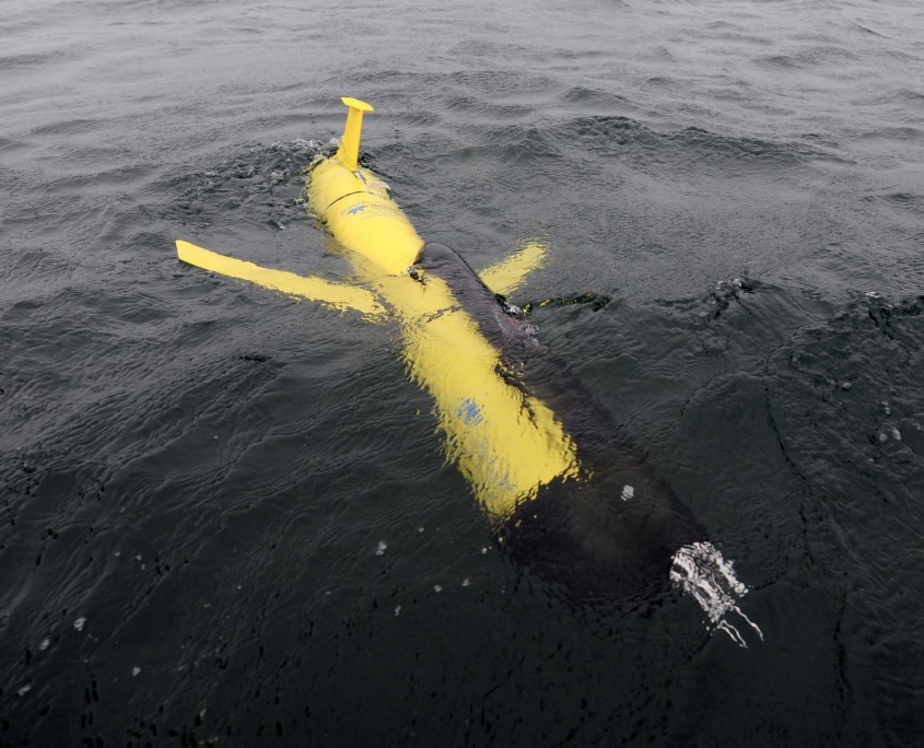
MicroRider on Slocum Glider


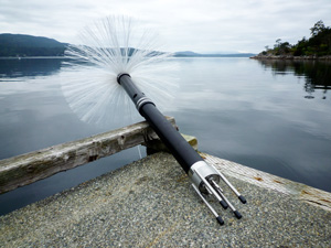
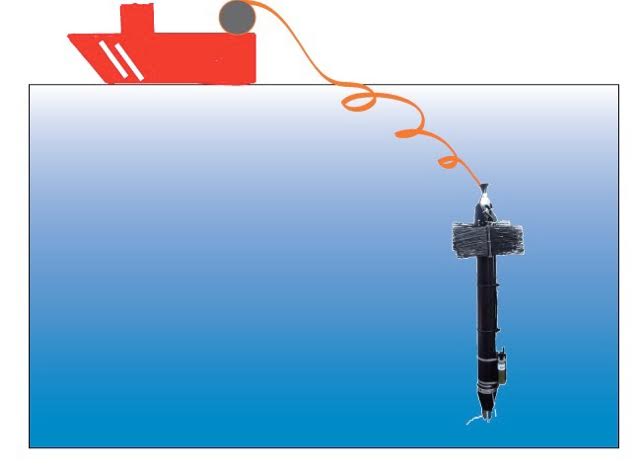
The MicroRider is a small instrument package for turbulence microstructure measurements, designed to integrate with a variety of marine instrument carriers, such as Gliders, AUVs, moorings, CTD rosettes, profiling floats and the WireWalker.

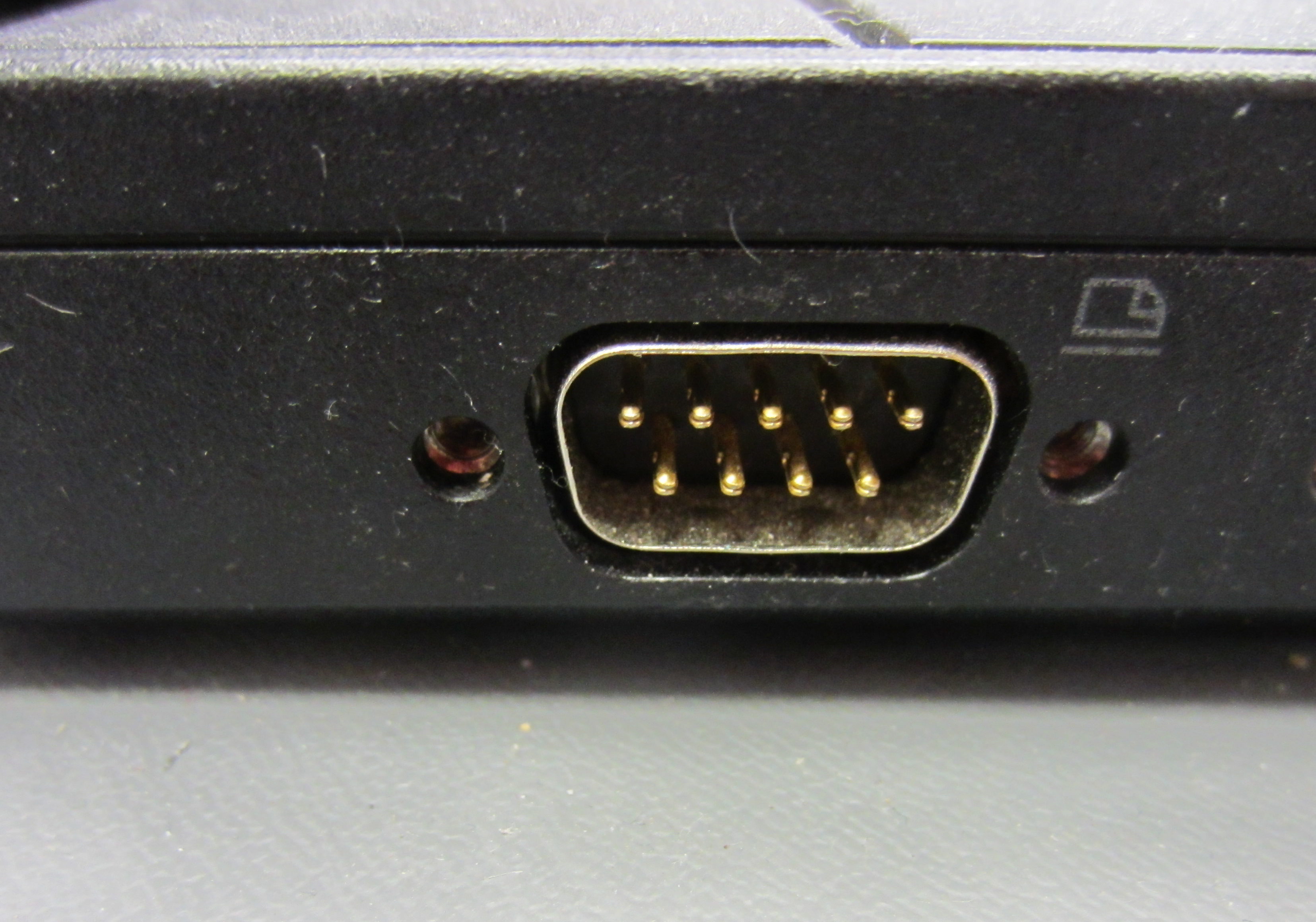
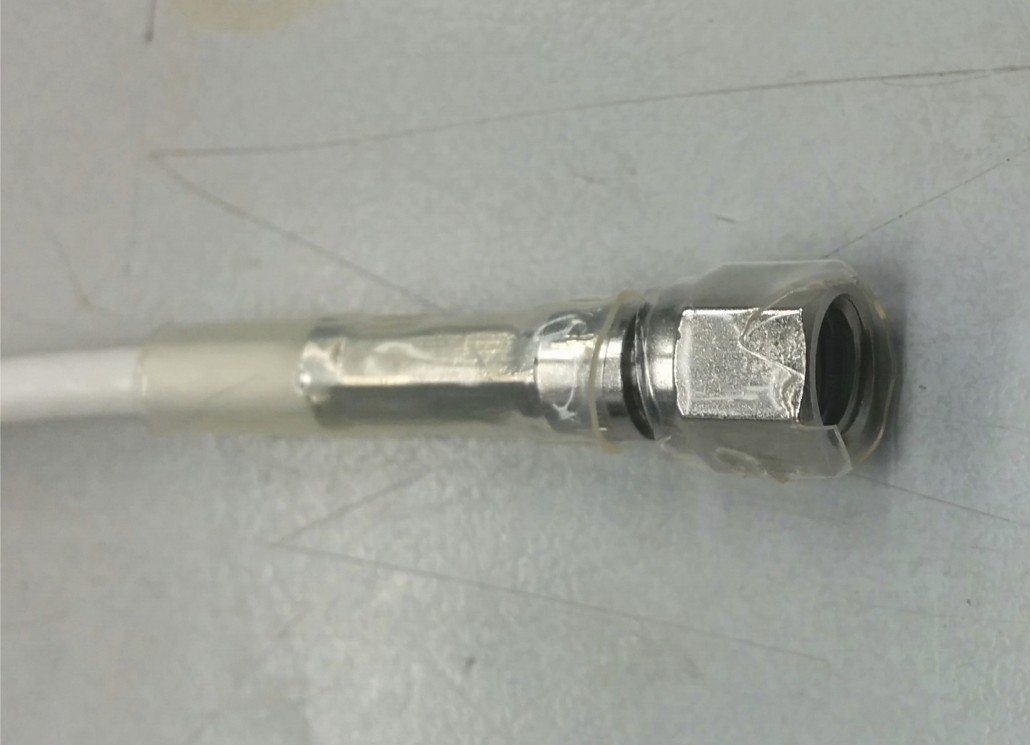
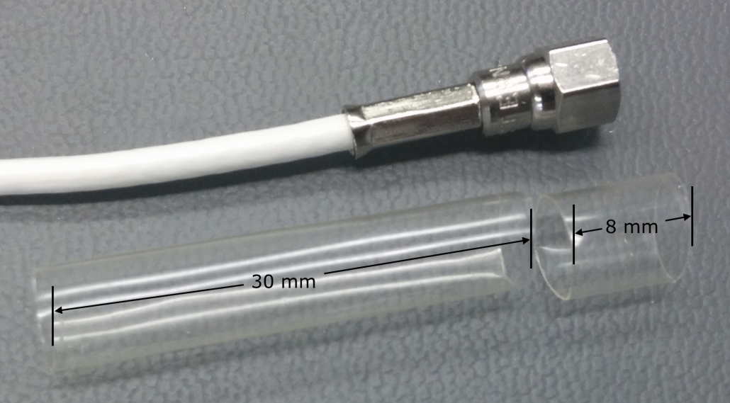
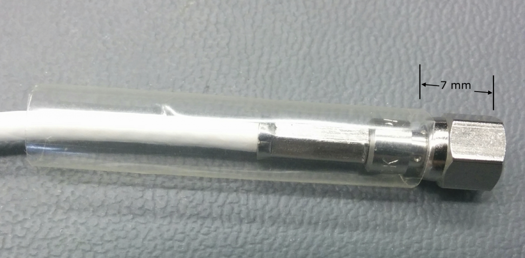
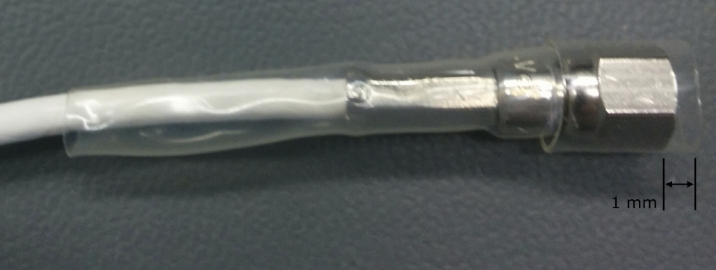
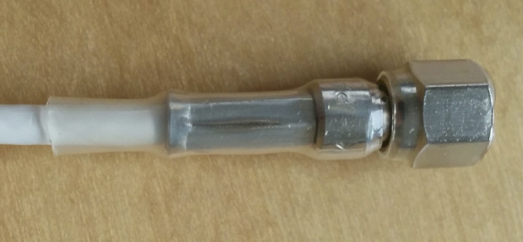
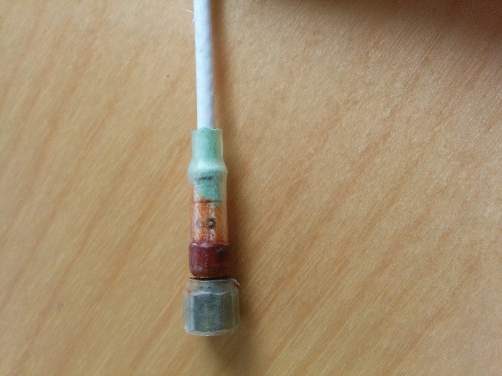
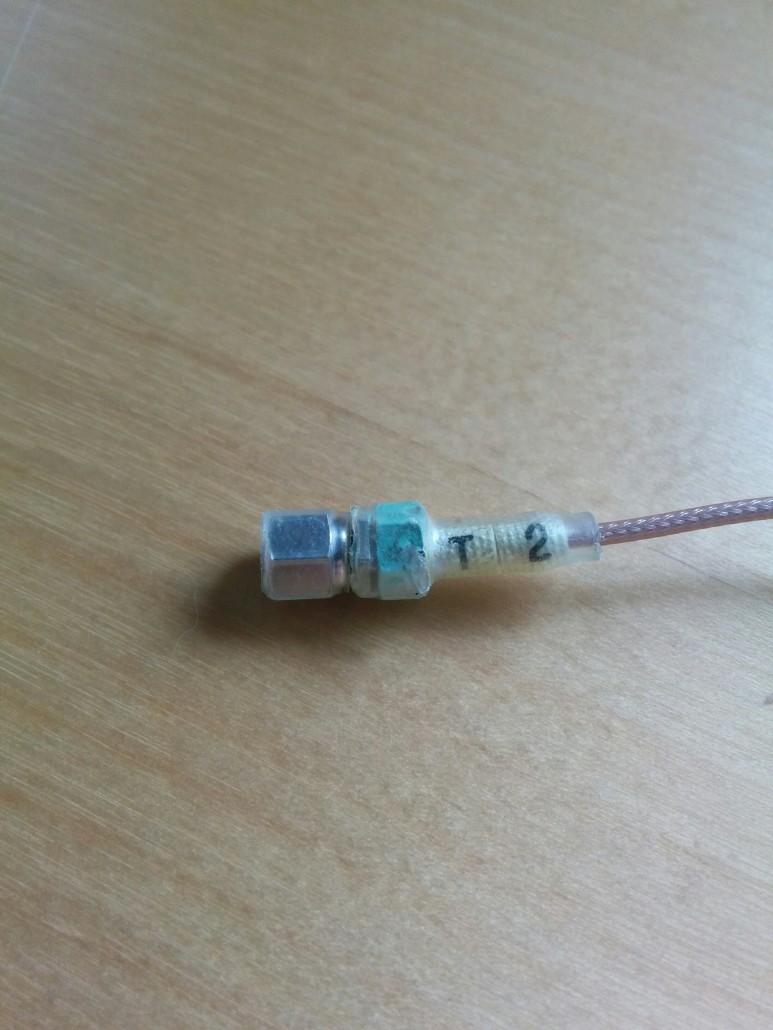
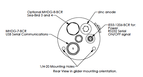
Depending on the age if your MicroRider instrument, it will either have an IE55-1206-BCR or a MCBH(WB)-8-FS connect on the rear end-cap.  This connector serves as the power supply, RS232 serial output and ON/OFF signal for the MicroRider. 


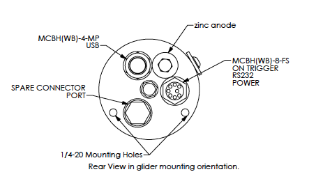
To power on your MicroRider, here is the startup sequence:

Using the connection to the IE55-1206-BCR or MCBH-8-MP connector, where:

Pin 1: +12VDC Power
Pin 2: Power Ground
Pin 3: Not Connected
Pin 4: Not Connected
Pin 5: RS232 TX
Pin 6: RS232 RX
Pin 7: ON Signal
Pin 8: ON Signal Return
  1. Connect the Power to Pin 1 and Pin 2. This power must always be available (on and live) to the MicroRider.  The power supply board has a low power watchdog circuit that checks the power. 
  2. If the power voltage is OK (within limits) than the power supply board waits for the ON signal to be activated. 
  3. The ON signal is connected to Pin 7 and Pin 8. It is either done by shorting across Pin7 and Pin8, or by sending a small current (1mA – 2mA) into Pin 7 and return on Pin 8. 
  4. When the ON signal is detected by the power supply board it energizes the MicroRider. 
  5. The internal computer boots up. 
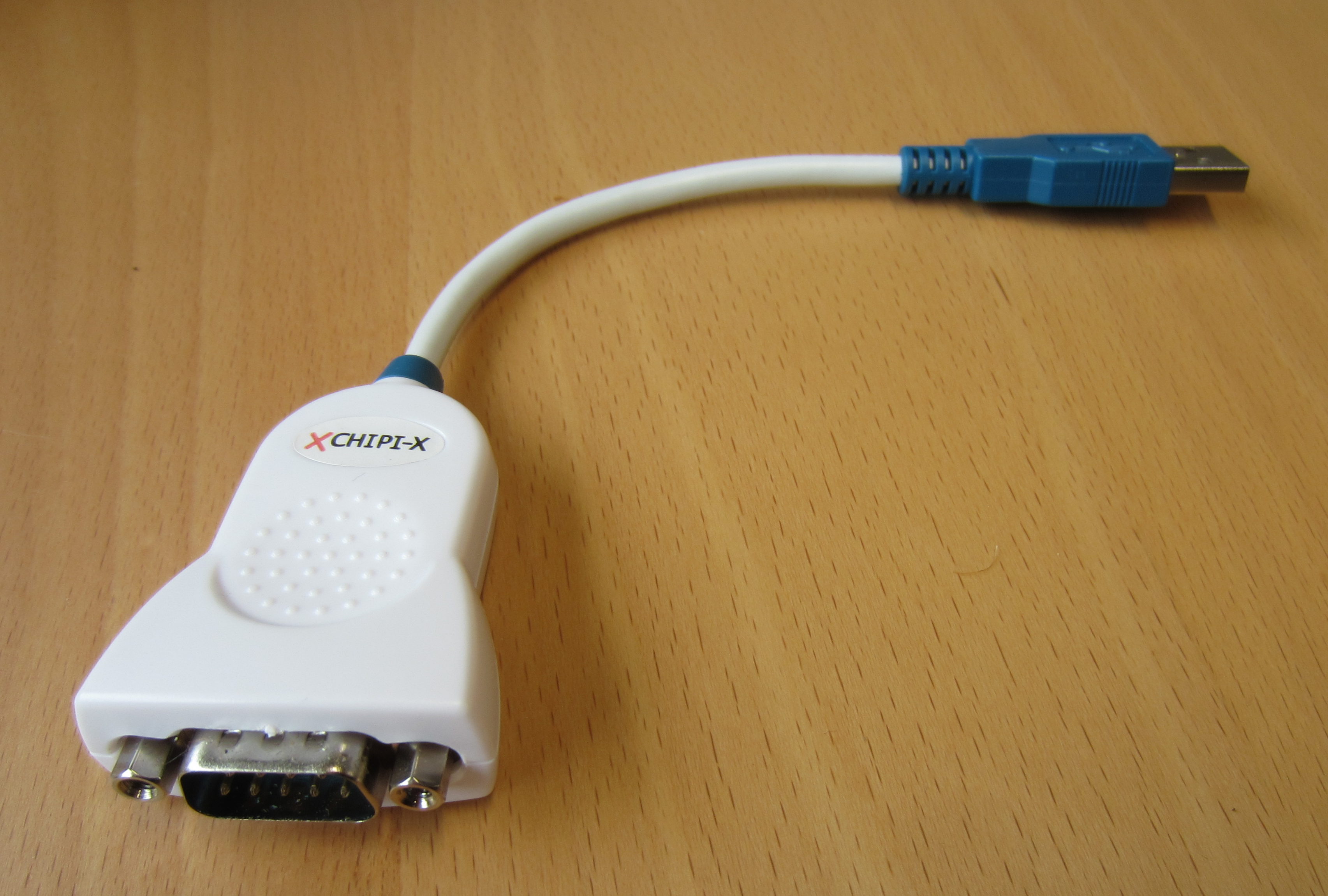
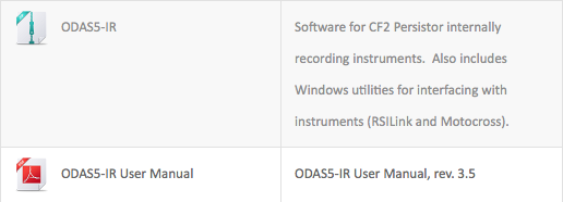
  6. At this time the customer RS232 connection on Pins 5/6 through a terminal program (Motocross) can be made so the customer has manual control of datalogging. Or, the computer can be set up so it automatically starts datalogging. 
  7. To safely shut off the MicroRider the customer must stop datalogging. 
  8. Then remove the ON signal which tells the power supply board to shutdown. 
  9. The MicroRider goes back to the very low power watchdog state waiting for the next ON signal. 

Basically: 

  • Power must always be available 
  • ON/OFF is controlled by the user through a shorting switch or using a small current driver 
  • Datalogging is either started automatically; or the user can manually control through the serial connection. 
  • Power must not be disconnected while datalogging or the onboard computer files will be corrupted and it will not work properly.

Limiting the Size and Duration of Data Files: autoexec.bat

When preparing for a long duration deployment it is important to consider the length of the data file that will be generated. MicroRiders are often deployed for days or weeks at a time. The default setting on Rockland instruments is to collect a single data file unlimited in size. A file collected over days or weeks can be unmanageable in post processing. Furthermore, a file can be lost if the instrument is turned off incorrectly while recording. To limit the size and duration of resulting data files use the flag -t followed by the number of records you would like in each file (1 record is approximately 1 second) . Please note that you will loose 30 to 40 seconds of data every time a file is written; users often use 3600 records (approximately 1 hour). To change your system to automatically use the command odas5ir -f setup.cfg -l 3000 -t 3600 you will need to change the autoexec.bat file:

1. Download the file to your data acquisition computer,
2. Edit the contents of the file to be odas5ir -f setup.cfg -l 3000 -t 3600, or the number of records you prefer,
3. Delete the existing autoexec.bat off the CF card,
4. Upload the new autoexec.bat file to the CF card.

Please note the flag -l 3000 sets the clock on the instrument. For instruments with the Tidal Energy Configuration, which use a sample rate of 1024Hz, the clock must be set to -l 6000.

Warning: Commands on the autoexec.bat file are case sensitive.

To learn more about PicoDOS commands, please review the ODAS5-IR User Guide. Please contact technical support to request a copy of the manual.

How to Make a Hotel File

MicroRider mounted on an ocean glider

In order to process data from a velocity shear probe the speed of the instrument or flow over the probes must be obtained. When using a Vertical Microstructure Profiler (VMP) the pressure data can be used to determine speed. However, pressure data cannot be used to obtain speed when profiling horizontally with a MicroRider. In most cases, speed must be determined by using an secondary source such as an acoustic doppler velocimeter, an electromagnetic flow sensor or speed records from an AUV or glider.

If your Rockland instrument is mounted on a vehicle that provides mission files, you may wish to integrate the data provided in the mission file into your data processing. In some cases the data recorded by the vehicle is required to process the p-file. There are currently four scripts and functions in the ODAS MATLAB Library for extracting information out of mission files and placing it into a hotel file.

The hotel file is ingested by odas_p2mat and interpolated on to the time vector t_slow in your p-file. The resulting data vectors are saved to the same mat-file as the data vectors produced from the p-files. The most common use of a hotel file is to import speed data from a vehicle when the Rockland instrument is not able to measure the speed itself (such as an AUV equipped with a MicroRider, or a Seaglider equipped with MicroPods). An accurate speed estimate is required to convert shear probe data into physical units and to compute gradients of temperature and conductivity. Other data of interest measured by the controller in a vehicle include CT data, pressure, pitch, roll and heading, for example.

If you would like to processes your data without a hotel file, please indicate a reasonable constant speed in meters per second. For example: odas_p2mat(‘file_name.P’,’constant_speed’,1.2)

For more information and an example of Hotel File setup, please review Section 10 of Technical Note 39.

Join us at our next OMG Workshop

If you are interested in learning more about Hotel Files, please join us for our annual Ocean Microstructure Glider Workshop (OMG Workshop).

Happy Holidays: Office closed from December 26-30

Please be advised that the Rockland Scientific office will be closed between December 26th to the 30th 2016. Everyone at Rockland wishes you a joyous holiday season especially if you find yourself at sea during this time.

If you require support over the holidays please do not hesitate to contact support@rocklandscientific.com. We will respond promptly to any inquiries.

Happy Holidays from everyone at Rockland Scientific International

Instrument Communication Troubleshooting

While operating a Rockland Scientific Microstructure Instrument you may experience difficulty with instrument communication. Here are some troubleshooting tips to help ensure reliable communication with your internally recording instrument.

In order to communicate, you will need your microstructure instrument, the instrument deck cable and a computer. You will need to connect to your computer via a USB port as well as a 9-pin RS-232 D-sub serial port. If you do not have a serial port on your computer you can use a RS-232 serial to usb adaptor cable. Not all adaptor cables are equal, so if you find one that works well for you then hang on to it!

9-pin RS-232 D-sub serial port

9-pin RS-232 D-sub serial port

RS-232 Serial to USB Adaptor

RS-232 Serial to USB Adaptor

Required Software

There is usually no need to install any software on the Persistor computer in your instrument because this will be done at Rockland before the instrument is shipped. However, you must install two programs on your computer. One is Motocross, which provides terminal emulation and serial communication with the instrument and permits the transfer of files, including executable software files. The other is RSI-link, a USB link utility that permits the bi-directional transfer of files between your computer and the instrument. All registered users can download Motocross and RSI-Link as part of a file called ODAS5-IR from the downloads section of our website. To register please fill out the required information under “Register”. You must make an account and receive authorization before downloading.

ODAS5-IR and ODAS5-IR User Manual in Downloads Section

ODAS5-IR and ODAS5-IR User Manual in Downloads Section

Mac vs PC

We recommend using a PC rather than a Mac computer. There are some work-arounds if you must use a Mac. The Motocross Terminal Emulator will not work on Mac computers so we recommend CoolTerm as a replacement for Motocross on Mac computers. CoolTerm allows for reliable communication and file transfers, however it will not allow you to reformat the CF card. For a complete work-around we recommend installing VirtualBox on your Mac and running Windows7.

Which version of windows is preferred?

The following versions of windows are supported: WindowsXP, Windows7, Windows8, Windows8.1, Windows10.

COM Port Number

Motocross has difficulty communicating with serial COM Ports that are not between 1 and 10. If you are having difficulty communicating please check your the serial COM port number and change if necessary. You can access COM ports by opening your Device Manager in the Control Panel while connected to your instrument.

USB 3.0 vs USB 2.0

We are currently experiencing difficulties with instrument communications through USB 3.0. Please use the USB 2.0 port on your computer whenever possible. If you do not have a USB 2.0 port you can use a USB 3.0 to USB 2.0 adaptor cable or hub.

Still having Communication trouble?

Please review your instrument manual and the ODAS5-IR manual or contact us if you would like more information regarding instrument communications.

VMP-200_dock_web


Winches Optimized for Turbulence Profilers

When choosing a winch for your turbulence profiler it is important to consider the deployment characteristics of turbulence profilers. Unlike a CTD Rosette, turbulence profilers descend in what is known as tethered free-fall. Tethered free-falling is when a profiler is allowed to fall uninterrupted and decoupled from the vessel and/or ocean surface motions. To achieve this, the tether must be coiled on the surface of the water by hand so that the profiler can take up the slack as it falls.

Tethered free-fall. Note the slack in the orange tether.

Tethered free-fall. Note the slack in the orange tether.

While there are many options available, it is important to find a winch that works well for your turbulence profiler. Some important considerations include the following:

Free wheeling is an important capability of winches optimized for turbulence profilers. Free wheeling is enabled by the addition of  clutch that can be disengaged. Free wheeling the winch allows for a single operator to pull line or cable off the winch. For shorter profiles it may be practical to mark the line at the depth desired, take that much line off the winch and form a coil on the deck before deploying the profiler. For longer profiles it is best to work with a partner; one person pulling line off the winch in free wheel mode and the other casting the line into the water.

PID-02 Winch with microCTD Turbulence Profiler aboard the R/V John Strickland

PID-02 Winch with microCTD Turbulence Profiler aboard the R/V John Strickland

Recovery of turbulence profilers is the most important function of a winch. In many cases it is impractical to recover the profiler by hand. Recovery by winch can speed up the process allowing for more profiles to be taken during a cruise. When using a real time instrument please remember to use a sheave that accommodates the bend radius of the telemetry cable. Automatic level winders are also a useful feature. If an automatic  level winder is not included a boat hook can be used to guide the cable/line back onto the winch.    

Real Time and Internally Recording Turbulence Profilers have different winch requirements. Real time profilers require a telemetry cable as well as a slip-ring to allow data to be transferred from the cable on the rotating winch drum to a deck cable and finally to a computer. Winches for internally recording profilers do not require a slip-ring and generally require a lower pull strength because they do not need to lift the heavy cable. Winches optimized for internally recording profilers are often smaller such as the PID-02 which can be lifted easily by two people and secured to the deck of smaller vessels.    

Rockland Scientific partners with A.G.O. Environmental to provide a wide range of winches. A.G.O.’s team recently joined the Rockland crew for a field trip as part of the VicTOR 2016 training week. You can read more about the field trip here:  A.G.O. Field Trip with Rockland Scientific

Formatting your CF card

ODAS5IR v4.0.0 Instrument Software

We have recently released ODAS5IR v4.0.0 instrument software (2019). If you are operating the new software please use the restore command to format the CF card. More information in the ODAS5IR 4.0.0 User Guide.

ODAS5IR v3.5 Instrument Software
If you are operating the older ODAS5IR v3.5 instrument software please follow the steps below to format the CF card:
To reformat your CF Card, you must be using a Windows computer.
  1. Connect your VMP to your PC using Motocross
  2. Download all data files you want to keep
  3. Reformat your c directory: >> format c:
  4. Create the data directory: >> mkdir data
  5. Transfer ODAS5IR executable.  Using the ’Transfer’ option:
    1. Transfer > Load odas5ir.RUN
    2. Type >> s odas5ir
  6. Transfer USBL executable.  Using the ’Transfer’ option:
    1. Transfer > Load usbl.RUN
    2. Type >> s usbl
  7. Transfer the non-executable file, setup.cfg and autoexec.bat
    1. Transfer > Load setup.cfg
    2. Transfer > Load autoexec.bat
We recommend typing dir between each setup to ensure that the previous step has been executed correctly.
Once you have reformatted your CF card, run a short bench test and ensure that you are acquiring data correctly and you are able to process the resulting p-file.
Cheers,
The Customer Support Team 

VMP-250 Deployment Techniques Training Video

Deployment of the VMP-250 requires that it is mechanically decoupled from the vessel. Watch this training video for tips on proper deployment techniques. Video taken from recent training outside of Victoria Harbour, British Columbia.


Replacing Clear Heat-Shrink Tubing on SMC cables

Each SMC cable that protrudes from the nose cone of a VMP, MicroRider, or MicroSquid is encased in 2 pieces of clear heat-shrink tubing. The clear tubing insulates the exposed metal of both the SMC cable shaft and the nut from the inner wall of the probe holder. Damaged tubing must be replaced so that the probe does not make electrical contact with the probe holder.

Damaged tubing

SMC cable with damaged heat-shrink tubing

NOTE: If your SMC cables have moisture damage, replacing the heat-shrink tubing is NOT a sufficient repair. The entire SMC cable must be replaced.

To replace the heat-shrink tubing:

1) Remove the old tubing using a pair of wire cutters to snip the length of the old tubing. Alternatively the old tubing can be easily pulled off the cable by reheating the tubing. Note that there is tubing on both the nut of the SMC cable and the shaft of the SMC cable. Both pieces must be removed. You should now have a clean, exposed SMC cable and nut. Do not remove the identification label from your SMC cable.

2) Cut two pieces of new clear heat-shrink tubing to length: one piece covers the nut on the end of the SMC cable, 8 mm, and one piece covers the metal shaft, 30 mm.

Heat shrink cut to length

SMC cable after the old tubing as been removed, and two pieces of replacement tubing that have been cut to length. Note that this cable has no identification label. Do not remove the identification label from your SMC cable.

3) Place the tubing over the shaft, 7 mm behind the threaded face of the SMC nut. The tubing should protrude slightly past the end of the metal shaft so that when the tubing shrinks it will cling to the top of the shaft.

The heat shrink tubing covering the shaft of the SMC cable before heat has been applied. The heat shrink is positioned \SI{7}{\milli\meter} behind the front of the nut

The heat shrink tubing covering the shaft of the SMC cable before heat has been applied. The heat shrink is positioned 7 mm behind the front of the nut.

4) Heat the tubing on the shaft, rotating the cable gently to ensure that all sides of the shaft are heated evenly . Do not overheat the tubing. Apply only enough heat to shrink the tubing until it touches the cable. Excessive heating will damage the tubing. The nut must be left to spin freely after the tubing has been applied.

5) Place the tubing over the nut . The tubing should protrude 1 mm past the threaded end of the nut. This will leave enough heat-shrink tubing to cup the base of the nut when heated.

nut_hs_1 copy

Tubing on shaft, partially heated, and new tubing on nut before heating

6) Heat the tubing on the nut, rotating gently to ensure all sides of the nut are heated evenly. Do not overheat the tubing. The tubing will shrink and tighten around the nut. Ensure that the nut is able to rotate freely.

Heatshrink on SMC cable before heating.

The SMC cable with one piece of heat-shrink tubing on the nut and one piece of tubing on the shaft. The nut can still rotate freely.


Identifying and Avoiding Moisture Damage in your Instrument

One of the most frequently occurring problems among our user group is moisture damage to the probes, SMC cables, and nose cone.  There are several reasons moisture damage may occur.

  • Poor installation of sensors: over-tightening or under-tightening the probe holder cap, or an ill-seated probe will compromise the integrity of the sealing surface.
  • Installing sensors in the rain: droplets of water on the SMC cable nut can wick up the cable and render the cable in-operable.
  • Damage to ferrules or o-rings.
IMG_20160219_131212

A rusted and corroded SMC cable.

If you are concerned that moisture damage has occurred, please inspect your instrument for the following:

  • The clear heat-shrink over the SMC cables and SMC nut is discoloured and yellow or green
  • Rust or green corrosion has formed on the SMC connector of the probes or dummy probes
  • Rust or green corrosion has formed on the water-tight feed-thru inside the nose cone of your instrument
  • Droplets of water are found inside the nose cone when you open the instrument.
IMG_20160219_133232

A corroded and discoloured SMC cable

If you identify any of these symptoms, please contact us immediately and provide a recent bench test and photos of the effected areas.  Depending of the severity and extent of the flooding, we may be able to provide replacements parts, or the instrument will need to return to the factory for repair.

To avoid moisture damage, never deploy an instrument if you are concerned about the integrity of sealing surfaces.  Before every deployment:

  1. Ensure that you are installing your probes correctly.
  2. Confirm the integrity of sealing o-rings.

If you are unfamiliar with installing sensors, practice installing the probes on land before you have departed on a ship.  We have a great YouTube video for your reference.