Vibrations Sensors: History, Signal Output and Calibration with Rockland Instruments
In 2010, 2-axis piezo-accelerometers (vibration sensors) and a precision inclinometer accurate to 0.1 degrees replaced three DC-response accelerometers in Rockland instruments. The new system produces far better low-frequency angle measurements and a much improved signal-to-noise ratio for higher frequencies. The purpose of the vibration sensors is not to quantify the acceleration of a VMP or MicroRider, but rather to produce a signal that is linear with respect to acceleration so that acceleration-coherent noise can be removed from the environmental signals measured by the shear probe.
The vibration sensors are piezo-ceramic beams that are anchored at one end and have a free cantilevered section over about one-half of their length. We glue a small weight near the tip in order to increase their sensitivity to vibrations. The signals from the beams are treated just like the signal from a shear probe. Thus, the sampled signal is proportional to the rate of change of acceleration and not to acceleration itself.
Rockland does not calibrate the sensors. Their sensitivity can vary by a factor of ~3.
Initially, we used the “type = accel” in the setup.cfg-configuration file to identify the piezo-vibration sensors. However, this is the same type that was used for DC-response accelerometers. This “type” requires two coefficients (coef0 and coef1) to convert the data into physical units. The piezo-accelerometers are not calibrated, so we used coefficients of “coef0=0″ and “coef1=1″, but this is not satisfactory because the second calibration coefficients has units of gravity and, consequently, the raw data are multiplied by a factor of 9.81.
Thus, we added a new signal type, namely “type = piezo”, to the identify the piezo-accelerometers It does not need any coefficient, but will accept an offset coefficient “coef0 = offset_value”, if available. The main reason for adding this new signal type is to keep the spectra of vibrations on the same scale as the spectra of shear. Many of the plotting functions in the ODAS Matlab Library can detect that the acceleration signals come from piezo-accelerometers and will adjust the scaling of piezo-accelerometer spectra so that they remain visible in a figure of spectra from mixed signals. We thus strongly recommend that you used “type = piezo” in your configuration file. If you use “type = accel” AND use coefficients of 0 and 1, then these functions will assume that the signal comes from a piezo-accelerometer and not from a DC-response accelerometer, for backward compatibility.
The piezo-accelerometrers are inherently AC sensors with a low-frequency cut-off at 0.1 Hz. In addition, we do not know the frequency response of the vibration sensors but estimate that it must be at least to1000 Hz based on the elastic and dimensional properties of the ceramic and the mass that is attached to its tip.
When referring to the the two vibration sensors in a Rockland instrument, we use the nomenclature Ax and Ay because these implied co-ordinates correspond to those of a vertical profiler. If you are using the MicroRider on a glider or an AUV, then the co-ordinates are rotated by 90 degrees around the y-axis. For example, Ax becomes Az, and Ay remains Ay.
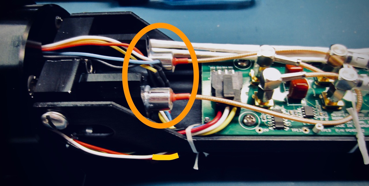
Two vibration sensors (Ax and Ay) embedded in front bulkhead block in the nose of the VMP-250 instrument. Signals from Ax and Ay are logged on the ASTP electronics board.